Introduction to a Speedometer project
I have a classic Mini that has been extensively modified by several different owners. The list of mods is long but the most significant is an engine swap to a Rover 1.8 vcc K-series engine. This chucks out about 3 times what the original engine would output and is some what lighter.
When I took ownership the interior was pretty bad. The seats were very uncomfortable bucket racing seats and the dash was made up from the donor car. The gauges had literallty been hacksawed out of the donor car and bolted behind some mdf.
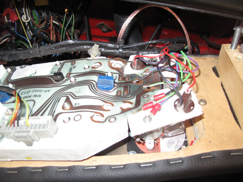 The fuel dial never showed more that half full, the temp gauge always sat at 90C (even when I drag raced it at Santa pod) and the speedo was typically 10-20% over generous. So I started a project to replace the dashboard... in about 2010
I found a great fibreglass dash piece that fitted the look of the car and so started to look of new gauges to put in it. Temperature and rev counter was no problem and I quickly found some cheap but good looking gauges that worked without much bother. Then came the speedo. The speed is calculated by the ECU using a sensor on the gearbox case but it assumes certain metrics like wheel diameter. This is why the old speedo was always over keen in what it thought the speed was. What is needed is a speedo that can be programmed to fit the vehicle. Now these do exist but are not cheap so I set about making one.
X25/X27 Switec automotive stepper motor
Most modern cars use a high precision stepper motor to drive the gauges. These were only sold to manufacturers initally and the first couple of motors I got hold of were very expensive and I had to get them direct from the swiss manufacturer as a sales sample (did not want 10,000). Now you can buy them on ebay for £2-3 each. They have 315 degrees of rotation in 1/3 degree increments and can run off 5-12v.
My first success was to drive it directly off the Arduino output pins and using the standard stepper motor library. The movement wasn't very smooth and lots of people warned about fly back current damaging the Arduino. If you spin a stepper motor it will generate current which can flow back up and damage control circuits. Obviously you just need a simple diode to protect against this.
After some serious googling about I found Guy Carpenters blog and his Gaugette project and he wrote a great library for the X25 https://github.com/clearwater/SwitecX25
#include "SwitecX25.h"

// 315 degrees of range = 315x3 steps = 945 steps
// declare motor1 with 945 steps on pins 4-7
SwitecX25 motor1(315*3, 4,5,6,7);

// declare motor2 with 945 steps on pins 8-11
SwitecX25 motor2(315*3, 8,9,10,11);

void setup(void) {
  Serial.begin(9600);
  Serial.println("Go!");

  // run both motors against stops to re-zero
  motor1.zero();   // this is a slow, blocking operation
  motor2.zero();
  motor1.setPosition(427);
  motor2.setPosition(427);
}

void loop(void) {
  // update motors frequently to allow them to step
  motor1.update();
  motor2.update();

  // do stuff, call motorX.setPosition(step) to
  // direct needle to new position.
}
This fixed all of my crude code and I got some great movement as seen in his videos.
Measuring speed
So obviously the ECU has a speedo data feed that is currently out of adjustment but I was sure if I could caputure the data with an Arduino I could make an adjustment before sending to the X25 gauge. The tachometer (rev counter) signal coming out of the ECU is a square wave that changes frequency as the revs change. My multi-meter has a frequency feature and this was easily confirmed that booting the throttle increased the frequency. You can use the Ardunino interupt pin to make a simple frequency counter and with a voltage divider I build a simple setup that did indeed measure the revs.
I was hopeful that the speed signal would be the same but alas it did not behave the same way. At this time I cannot find any documentation as the Rover ECU is propriatary and one day hope to crack this puzzle. I need a oscilloscope or logic analyser to get any further. If anyone has any clues on this then please let me know.
So plan B is to use GPS, which has the benefit of being more accurate (some of the time) and auto calibrating. I went for the Adafruit Ultimate GPS logger shield as it is a very sensive unit with 10Hz update rate and 66 channels. I also liked the fact it had onboard SD card for data logging.
Tindie Serial killer
While browsing Tindie I saw that someone had mounted a X25/27 to a board and added all of the protection and isolation I was planning to add. They had taken this even further and added a ATTINY Microcontoller to control the gauge via a serial interface. This was great as now all I needed to do on the arduino is to parse the speed over ground from the GPS data and send it to the gauge, which is as simple as sending Serial.println(100)
This is simplifed from the actual code to keep it nice and readable but this is the core of it:
#include <Adafruit_GPS.h>
#include <SoftwareSerial.h>

//I am using an uno so need a software serial port
SoftwareSerial mySerial(8, 7);
Adafruit_GPS GPS(&mySerial);

float knotsToMPH = 1.15077945;
int speedInMPH = 0;
int hoursToSeconds = 3600;
float delta_t;
float distanceTraveledInMiles = 0.0; //increases as user goes farther

// motor ranges from 0-944 but the display is clipped
#define ZERO_POSITION 100 // 0 on the speedo
#define MAX_POSITION 700 //70 on the speedo
int gaugePosition = ZERO_POSITION;

void setup() {
  // connect to gauge controller
  Serial.begin(2400);

  // Connect to GPS
  GPS.begin(9600);

  //Set gauge to start end stop
  Serial.println(0);
  delay(2000);

}

void loop()
{
    if (GPS.fix) {
      distanceTraveledInMiles = distanceTraveledInMiles+GPS.speed*knotsToMPH/hoursToSeconds*delta_t;
      speedInMPH = (int) GPS.speed*knotsToMPH;
      gaugePosition = (int)(speedInMPH * 7.5 ) + ZERO_POSITION;
      Serial.println(gaugePosition);

    }else{
      // Sweep back and forth to show the GPS is searching of a fix
      Serial.println("372");
      delay(1000);
      Serial.println("572");
      delay(1000);
    }

}
It did take some trial and error to find the magic multiplier of 7.5 which converted the speed to degrees on the stepper. I am sure someone with better maths skills than me could calculate this but I just guesstimated it and then tweeked until it was right.
Case
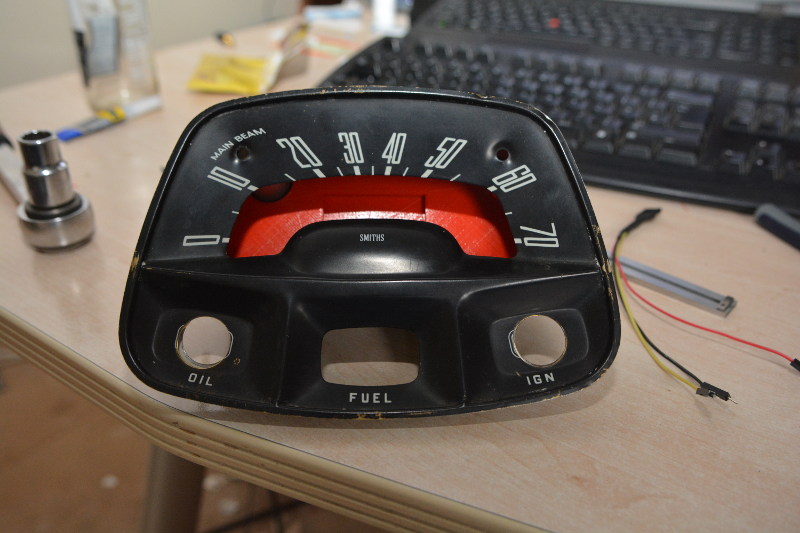
I wanted something retro to fit in with the classic Mini style. Old mechanically driven speedos are all over ebay and I stated buying up a few with the aim of removing the guts and reinstalling the stepper. My favourite was a Mach display from a spitfire but I could not bring myself to destroy it and also it has two needles much like a hour and minute hand of a clock. This would be too tricky. Then I found something at a car boot which turned out to be from old Austin A30/40 cars.
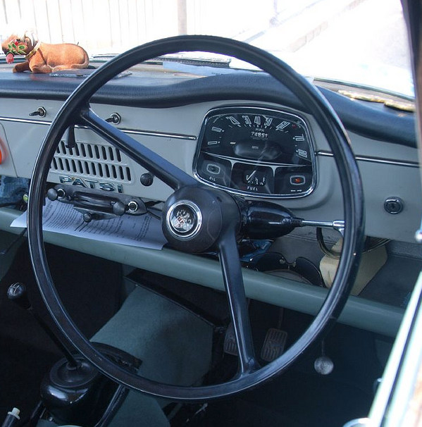
I liked the style and that it was a all in one unit. I removed the internals and started thinking about how to mount the stepper motor board. It needed to be quite a precise distance from the metal top plate. I started off with some mechano because that is what was on my desk but it became clear this was job for the 3d Printer.
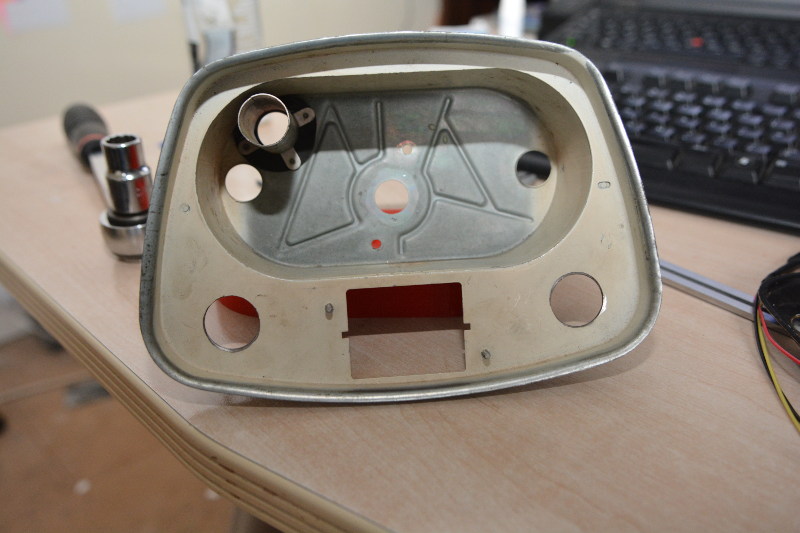
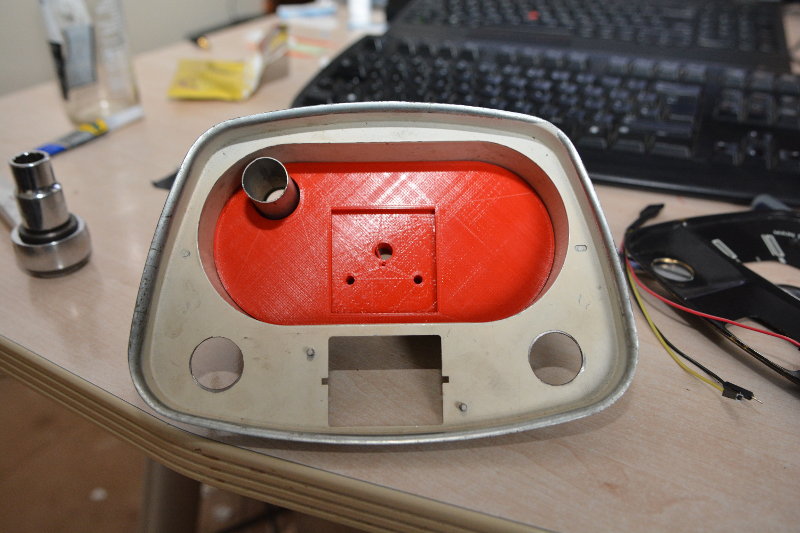
I grabbed some capliers and started drawing 2d shapes in Sketchup. The base oval was a 75mm square with two semi-circles attached to each end. I started with the square and used the arc tool to round off the ends. A hole was needed for the top right and this was very tricky to measure. I made a couple of prints just a few layers thick until i had this dialed in enough so it would fit.
I then extruded the whole shape up to around 15mm which is what I had calculated to be the thickness I needed to get the gauge needle in the right place. I added a small recess to acommodate the board and some holes for the mounting screws. Turned out I had put these in totally the wrong spot. Nevermind, nothing some double sided tape won't fix in the short term.
 Tight enought that there is no rattle. The following shot is with the face plate on.
Next job was so real world testing and so I thought I had better put the Ardunio in a case so I headed over to Thingiverse and found this nice Snug case. This is where a 3d printer becomes really useful. Buying a case would cost at least £10 and take a day or two if I could find the exact one I wanted. I could browse several different cases and pick the one most suited and in less than an hour the Arduino was inside and attached to the back of the speedo.
Finally a quick video of the startup and the GPS gettng a fix